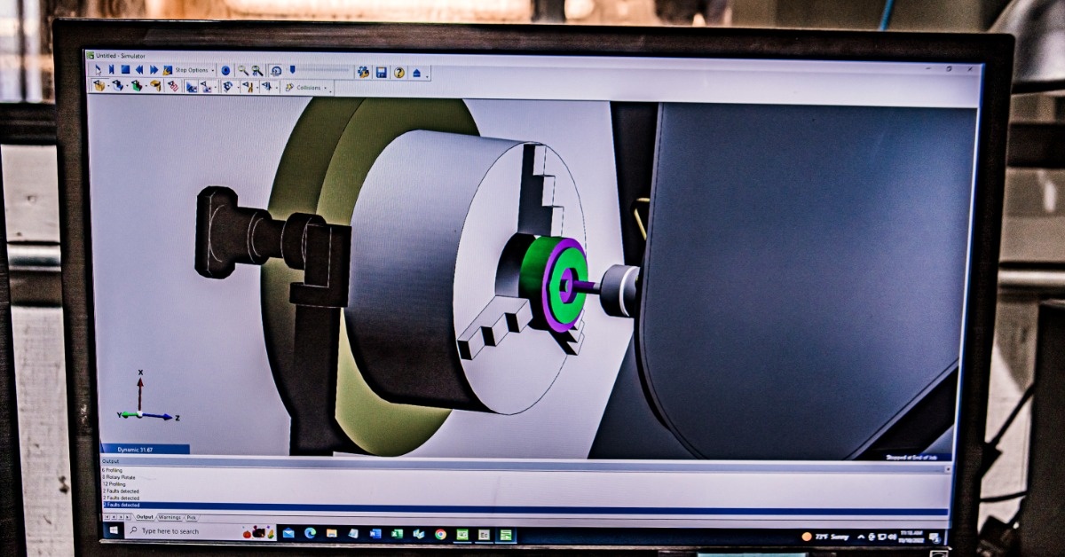
Designing CNC-machined plastic parts requires more than transferring metal-part practices to a different material. Plastics respond differently to cutting forces and environmental changes. Those characteristics can influence dimensions during machining and after the component enters service.
Engineers can prevent many production challenges by considering machinability during the design stage. Material properties, geometry, tolerances, and workholding requirements should support one another. This approach helps manufacturers produce accurate components while controlling unnecessary complexity.
For demanding industries, small design choices can carry significant consequences. When engineers understand design rules for CNC plastic machined parts, it gives precision machining processes the conditions needed to succeed. It also supports repeatability when production moves beyond initial prototypes.
Select the Material Before Locking in Dimensions
Material selection should guide component design rather than occur after engineers finalize the geometry. High-performance polymers differ in stiffness, thermal expansion, wear behavior, and chemical resistance. Those differences can influence achievable dimensions and long-term stability.
Operating conditions provide an important starting point for material selection. Semiconductor equipment may require dimensional stability and cleanliness, while oil and gas applications can introduce chemical exposure and elevated temperatures. Aerospace components may encounter substantial temperature changes while also facing strict weight requirements.
Engineers should compare those demands against the properties of the proposed polymer. A material that works well for one precision component may create unnecessary challenges in another application. Selecting the appropriate material early makes later design decisions easier to evaluate.
Apply Tight Tolerances Strategically
Precision machining can achieve demanding tolerances, but engineers should not automatically apply the tightest possible tolerance to every dimension. Restrictive tolerances increase machining and inspection requirements. They can also complicate production when the dimension has little influence on component performance.
Designers should identify dimensions that directly affect fit, sealing, alignment, movement, or another critical function. Those features deserve the greatest dimensional control. Less important surfaces can often accept wider tolerances without affecting how the finished assembly operates.
Plastics also require special consideration because temperature can influence dimensions more noticeably than it does with many metals. Inspection conditions and expected operating temperatures may therefore matter when establishing tolerances. Functional requirements should determine the specification rather than an arbitrary preference for tighter numbers.
Keep Wall Thickness Practical
Thin walls can create challenges during CNC machining because cutting forces may cause the material to flex. Clamping pressure can also distort delicate sections before the cutting tool reaches them. Even minor movement can affect dimensions when a component requires ultra-tight tolerances.
Whenever the application permits, designers should provide enough wall thickness to support the component during machining. Additional material can improve rigidity and give the machinist more control over critical features. Engineers still need to balance this consideration against weight, clearance, and functional requirements.
Use Machinable Internal Radii
CNC cutting tools rotate, which means they cannot create perfectly sharp internal corners. Engineers should design internal radii that accommodate practical cutter sizes whenever the component allows. A larger radius can often make a significant difference in machining efficiency.
Very small internal radii may require equally small cutting tools. Smaller tools generally offer less rigidity and may require more conservative machining parameters. That combination can increase production time even when the small radius provides no functional advantage.
Pockets, shoulders, channels, and slots deserve particular attention during design reviews. Engineers should determine whether each internal corner truly requires a small radius. Increasing noncritical radii can simplify tool selection while preserving the component’s intended function.
Design Holes Around Real Machining Conditions
Holes may look straightforward in a CAD model, but their dimensions and locations can introduce significant machining challenges. Deep holes require tools to reach farther into the workpiece while maintaining rigidity. Small diameters can further restrict chip removal and complicate heat management.
Engineers should consider the relationship between hole diameter and depth before finalizing the feature. They should also leave adequate material around holes whenever the component geometry permits. Holes located too close to thin edges can reduce support in already delicate areas.
Several practical rules can improve hole design:
- Keep hole depth reasonable relative to its diameter.
- Provide sufficient material around critical bores.
- Avoid unnecessary holes near thin edges.
- Clearly identify thread and tolerance requirements.
- Reserve extremely tight specifications for functional features.
These choices give machinists greater flexibility when selecting tools and developing machining strategies. They also help prevent a secondary feature from becoming one of the most difficult areas of the component. Well-planned holes support both dimensional control and production efficiency.
Account for Temperature Changes
Heat plays an important role when machining precision plastic components. Cutting creates heat where the tool contacts the material, and plastics can respond to that temperature change differently than metals. Machining strategies must control heat to protect dimensional accuracy and surface quality.
The operating environment can introduce another temperature range after manufacturing. A component that meets dimensional requirements at inspection temperature may expand or contract during service. Engineers should account for this behavior when critical clearances or mating relationships depend on dimensional stability.
Geometry can also influence the effects of temperature. Long, thin sections may react differently than compact features with larger cross sections. Communicating expected operating temperatures gives the machining team valuable context when reviewing demanding dimensional requirements.
Consider Workholding Before Production
A machinist must hold the workpiece securely while cutting tools create the required geometry. Designers sometimes overlook this basic requirement when developing complex parts. A component with few stable clamping surfaces can require specialized fixtures or additional manufacturing steps.
Plastic creates another consideration because excessive clamping pressure may distort the workpiece. Insufficient pressure, however, can allow movement during machining. Good component geometry gives machinists practical surfaces to locate, support, and secure the material without compromising critical areas.
Multiple setups can further complicate dimensional relationships between features. Engineers can help by establishing logical datum surfaces that support both machining and inspection. Working with a custom plastic machining specialist during development can reveal workholding concerns before the design reaches production.
Design for Inspection and Repeatable Production
Manufacturers need a reliable way to verify that finished components meet engineering requirements. Clear datums provide common reference points for machining and inspection. Designers should dimension critical features from references that support consistent measurement rather than creating unnecessary interpretation.
Engineering drawings should clearly communicate materials, tolerances, threads, surface requirements, and other important specifications. Ambiguous dimensioning can cause problems when several precision features interact. Clear documentation becomes especially important when components require ultra-tight tolerances across multiple production runs.
Build Manufacturability Into the Part From the Start
Following effective CNC plastic design rules connects material behavior with geometry, tolerances, and workholding. Engineers gain more control when they consider these factors before releasing a final drawing. Early decisions can eliminate manufacturing challenges that become expensive to correct later.
Collaboration with an experienced plastics machining team can also identify opportunities that remain difficult to recognize from a CAD model alone. Plastics Machining specializes in custom precision-machined components with ultra-tight tolerances for demanding technical industries. Its experience includes aerospace, medical, energy, oil and gas, scientific instrumentation, semiconductor equipment, and industrial machinery.
Designing with machining realities in mind helps turn demanding specifications into accurate, repeatable components. Thoughtful geometry gives precision CNC processes a stronger foundation while helping control unnecessary production complexity. The best results start when engineers treat manufacturability as part of the design itself.

Leave A Comment